The Dynamic Audio Sensor is an asynchronous event-based silicon cochlea. The board takes stereo audio inputs; the custom chip asynchronously outputs a stream of address-events representing activity in different frequency ranges. As such it is a silicon model of the cochlea, the auditory inner ear. The system has also been called AER-EAR, where AER stands for Address-Event Representation – the protocol used to transmit spikes.
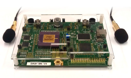
Fig. 1. Dynamic Audio Sensor USB board (DAS1), with on-board microphones, preamplifiers, and digitally controlled biases.
The Dynamic Audio Sensor (DAS1) is a binaural cochlea intended for spatial audition and auditory scene analysis. It is explained most thoroughly in this paper: Liu et al 2014. It uses cascaded second-order sections (SOS) to model the physical oscillation of the basilar membrane. These drive half-wave rectifier circuits, which model inner hair cells. These in turn drive multiple pulse frequency modulator circuits, which model ganglion cells with different spike thresholds. The resonance of individual sections can be adjusted with local digital-to-analog converters. This chip includes a variety of features including a matched binaural pair of cochleas, on-chip digitally controlled biases, on-chip microphone preamplifiers, and open-sourced host software APIs and algorithms. A bus-powered USB board enables easy interfacing to standard PCs for control and processing (Fig. 1), whilst a parallel AER port allows direct connection to other dedicated spiking neuromorphic hardware. The responses of the binaural DAS to speech and a chirp are shown in Fig. 2 and Fig. 3 respectively.
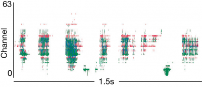
Fig. 2. Response to speech “The quick red fox jumped over the lazy dog”. The different colors correspond to channels of the different ears. Each dot is one event. The mean event rate is 17keps.
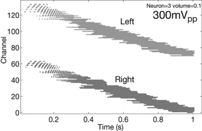
Fig. 3. Event rasters recorded from the 64 channels of both ears. Frequency is logarithmically swept from 30Hz to 10kHz with input amplitude 300mVpp.
Spike-Based Auditory Processing
Localization
The timing information from the DAS can be used for inferring the location of an acoustic source, for example, from the interaural time differences between sounds arriving to the two ears [37] or by emulating the echolocalization mechanism of bats (Abdalla and Horiuchi, 2005). The spike outputs can also be used to extract higher-level auditory features suitable for tasks such as harmonicity detection (Yu et al, 2009) and speaker identification (Liu et al, 2010b).
One useful application of the binaural DAS is in the extracted of localization cues. One of the main cues is the interaural time difference (ITD) cue. This cue comes from the difference in the timing arrival of sound waves at the two ears from a sound source can code for the location of a sound source in the azimuth direction. The use of the spike timing arrival difference of the output spikes of the binaural DAS can be used for sound localization (Chan et al, 2007). The data in Figure 9 of this work show how well the reconstructed ITD matches the actual source ITD illustrating that the address events preserve timing information for the extraction of interaural time differences.
An on-time localization algorithm running in jAER can be used to extract the sound location with approximate resolution and lower latency than using a cross-correlation algorithm on the microphone outputs (Holger and Finger, 2011).
Speaker Verification
An early experiment involving speaker identification on the TIMIT database (Liu et al 2010) with 20 males and 20 females together with Mesgarani and Hermansky shows possibilities of spike coded features from the DAS outputs. Three different feature sets are extracted in identifying speakers: 1) average ISI across channels 2) average ISI across time and 3) combination of 1 and 2. Classification was performed by training 40 linear Support-Vector-Machines (SVM) for each speaker versus the remaining speakers. The results show that the classification error of the speakers reduces over longer durations of speech.
DAS1 Design
The binaural chip has two separate 64-stage cascaded filter banks allowing connection to two electret microphones. The architecture of one of the two cochleas on the chip is shown in Fig 1. Each cochlea consists of a 64-stage cascaded filter bank stage. The cascaded architecture is preferred over a coupled bandpass architecture so we can achieve better matching and sharp high frequency roll-off. The coupled architecture is particularly susceptible to destructive interference at mismatched stages. A voltage-mode implementation is chosen over a current-mode implementation because of better robustness to fabrication variances. The impact of the smaller linear input range is reduced by including global automatic gain control (AGC) on the front of the filters, using off-chip microphone preamplifiers. The voltage-mode filter bank implementation also reduces variability compared with log-domain current-mode implementations which are very susceptible to current copying mismatch. However, noise accumulation and time delay along the cascade favor a small number of sections per octave, making it harder to maintain high Q. But maintaining acceptably high Q is important for spectral selectivity and is why this chip includes Q adjustment and lateral suppression circuits, as will be explained.
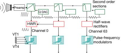
Each filter stage consists of a second-order-section (SOS) filter which is biased by a Complementary Lateral Bipolar Transistor (CLBT) ladder to improve matching [11]. A differential readout of each SOS output drives its own halfwave rectifier (HWR) circuit, and the HWR output drives 4 pulse-frequency modulators (PFMs). The PFM circuits implement an integrate-and-fire model with a threshold (VT). The four PFMs have individual global thresholds (VT1 to VT4), allowing volume encoding by selective activation of PFMs. Compared with regularly-sampled audio systems, the PFM outputs are transmitted asynchronously, reducing latency to the analog delay along the filter bank and increasing temporal resolution to microseconds.
The resonance of individual sections can be adjusted by a local digital-to-analog converter (QDAC). This chip includes a variety of features including a matched binaural pair of cochleas, on-chip digitally controlled biases, on-chip microphone preamplifiers, and open-sourced host software APIs and algorithms – the highly-usable USB2 implementation, and the jAER event-based processing software. A bus-powered USB board enables easy interfacing to standard PCs for control and processing (Fig. 9).
System Integration
The DAS1 is integrated with a USB2.0 high-speed interface that plugs into any PC or laptop. The host software presently stands at >200 Java classes. The open source jAER software project lets you render events in a variety of formats, capture them, replay them, and most important, process them using events and their precise timing.
Specifications
| Functionality | Asynchronous cochlea + ganglion cell output |
| Fabrication process | 4M 2P 0.35um standard CMOS |
| Channel count | 64×2 |
| Chip size size mm2 | 3.5 x 6 |
| Chip interface | 12-bit word-parallel AER active low Req and Ack 4-phase handshake |
| Computer interface | USB 2.0, Windows XP driver Java API & Matlab output file format |
| Power consumption | Chip: 18.4mW to 26mW (DVdd) 33mV (AVdd) USB System: approx. 70mA |
| Dynamic range to produce PFM output |
36dB (25mVpp to 1500mVpp) at microphone preamp output |
| Frequency range | 50Hz to 20kHz (adjustable) |
| PFM Best characteristic frequency (BCF) matching |
+-16% between ears at 150mVpp |
| PFM Q and Q matching (BCF/width at 0.7 of BCF) |
1.5 +- 0.4 (+-27%) at 450mVpp |
| Event timing jitter, 1kHz input | +- 2mus at 250mVpp |
| PFM peak bandwidth | 10M events/sec |
| Total PFM typical speech rate | 20k events/sec |
Acknowledgements
Dr. Shih-Chii Liu is the prinicipal researcher behind the DAS. This neuromorphic chip project started off as a colloborative effort between Shih-Chii Liu and Andre van Schaik. Subsequently, Tobi Delbruck, and Bradley Minch contributed to the design of some circuits on chip; and T. Delbruck and R. Berner to the development of the infrastructure surrounding the chip. This development was supported by the Institute of Neuromorphic Engineering Grant and the Office of Naval Research NICOP grant. Ongoing support is provided by the Inst. of Neuroinformatics through the University of Zurich and the Swiss Federal Institute of Technology (ETH Zurich).
References
Event-Based Output Designs
[1] S-C. Liu, A. van Schaik, B. A. Minch, and T. Delbruck, “Event-based 64-channel binaural silicon cochlea with Q enhancement mechanisms,” In Proceedings of the IEEE International Conference on Circuits and Systems, pp. 2027-2030, 2010.
[2] B. Wen and K. Boahen, “A silicon cochlea with active coupling”, IEEE Trans. on Biomedical Circuits and Systems, 3(6):444-455, 2009.
[3] V. Chan, S.-C. Liu, and A. van Schaik, “AER EAR: A matched silicon cochlea pair With Address Event Representation interface”, IEEE Transactions on Circuits and Systems I: Regular Papers, vol. 54, pp. 48-59, 2007.
[4] E. Fragniere, “A 100-channel analog CMOS auditory filter bank for speech recognition”, IEEE ISSCC Dig. of Tech. Papers, pp. 140-589, 2005.
[5] H. Abdalla and T. Horiuchi, “An ultrasonic filterbank with spiking neurons”, IEEE Intl. Symp. on Circuits and Systems (ISCAS 2005), pp. 4201-4204, 2005.
[6] R. Sarpeshkar, MS. Baker, JJ. Sit, L. Turicchia, and S. Zhak, “An analog bionic ear processor with zero-crossing detection”, IEEE ISSCC Dig. of Tech. Papers, pp. 78-79, 2005.
Analog Designs
[7] A. van Schaik, E. Fragniere, and E. A. Vittoz, “Improved silicon cochlea using compatible lateral bipolar transistors”, in Advances in Neural Information Processing Systems 8, pp. 671 – 677, 1995.
[8] J. Georgiou and C. Toumazou, “A 126-uW cochlear chip for a totally implantable system”, IEEE J. of Solid-State Circuits, 40:430-443, 2005.
[9] A. Katsiamis, E. Drakakis, and R. Lyon, “A biomimetic, 4.5uW, 120+ dB, log-domain cochlea channel with AGC”, IEEE Journal of Solid-State Circuits, 44:1006-22, 2009.
[2] R. F. Lyon and C. Mead, “An analog electronic cochlea”, IEEE Transactions on Acoustics, Speech, and Signal Processing, vol. 36, pp. 1119-1134, 1988.
[4] L. Watts, D. A. Kerns, R. F. Lyon, and C. A. Mead, “Improved implementation of the silicon cochlea”, IEEE Journal of Solid-State Circuits, vol. 27, pp. 692-700, 1992.
[7] L. Watts, “Cochlear mechanics: Analysis and analog VLSI”, Phd Thesis, California Institute of Technology, Pasadena, CA, 1992.
[10] A. van Schaik and E. Fragniere, “Pseudo-voltage domain implementation of a 2-dimensional silicon cochlea”, pp. 185-188 vol. 2, 2001.
[12] T. J. Hamilton, C. Jin, A. van Schaik, and J. Tapson, “An active 2-D silicon cochlea”, IEEE Transactions on Biomedical Circuits and Systems, vol. 2, pp. 30-43, 2008.
[13] T. J. Hamilton, J. Tapson, C. Jin, and A. van Schaik, “Analogue VLSI implementations of two dimensional, nonlinear, active cochlea models”, in 2008 Proceedings of IEEE Biomedical Circuits and Systems Conference, pp. 153-156, 2008.
[14] A. van Schaik and E. Fragniere, “Design of a 2-dimensional, pseudo-voltage-domain, silicon cochlea”, in ICSC Symposia on Intelligent Systems and Applications Canada, 2000.
[15] R. Sarpeshkar, R. F. Lyon, and C. A. Mead, “An analog VLSI cochlea with new transconductance amplifiers and nonlinear gain control”, vol. 3, pp. 292-296, 1996.
[16] R. F. Lyon, “Automatic gain control in cochlear mechanics”, in The Mechanics and Biophysics of Hearing, P. Dallos, Ed.: Springer-Verlag, pp. 395-402, 1990.
[17] C. D. Summerfield and R. F. Lyon, “ASIC implementation of the Lyon cochlea model”, in Proceedings of 1992 IEEE International Conference on Acoustics, Speech, and Signal Processing, ICASSP-92, vol. 5, pp. 673-676, 1992.
[18] R. Sarpeshkar, R. F. Lyon, and C. Mead, “A low-power wide-linear-range transconductance amplifier”, Analog Integrated Circuits and Signal Processing, vol. 13, pp. 123-151, 1997.
[19] T. J. Hamilton, J. Tapson, C. Jin, and A. van Schaik, “A 2-D silicon cochlea with an improved automatic quality factor Control-Loop”, in 2008 Proceedings of the International Symposium on Circuits and Systems, Seattle, USA, 2008.
[20] M. A. Ruggero, “Responses to sound of the basilar membrane of the mammalian cochlea”, Current Opinion in Neurobiology, vol. 2, pp. 449-456, 1992.
[21] M. A. Ruggero, L. Robles, and N. C. Rich, “Two-tone suppression in the basilar membrane of the cochlea: mechanical basis of auditory-nerve rate suppression”, vol. 68, pp. 1087-1099, 1992.
[22] L. Robles, M. A. Ruggero, and N. C. Rich, “Two-tone distortion on the basilar membrane of the Chinchilla cochlea”, vol. 77, pp. 2385-2399, 1997.
[23] R. Stoop, T. Jasa, Y. Uwate, and S. Martignoli, “From hearing to listening: Design and properties of an actively tunable electronic hearing sensor”, Sensors, vol. 7, pp. 3287-3298, 2007.
[24] R. Meddis, “Simulation of auditory-neural transduction: Further Studies”, J. Acoust. Soc. Am., vol. 83, pp. 1056-1063, 1988.
Spike-Based Processing
[1] M. Abdollahi and S-C. Liu,”Speaker-independent isolated digit recognition using an AER silicon cochlea,” In Proceedings of the IEEE Biomedical Circuits and Systems Conference, San Diego, CA, 2011.
[2] H. Finger and S-C. Liu, “Estimating the location of a sound source with a spike-timing localization algorithm”, IEEE International Symposium on Circuits and Systems 2011 (ISCAS 2011), 2011.
[3] S-C. Liu, N. Mesgarani, JG. Harris, and H. Hermansky, “The use of spike-based representations for hardware audition systems”, IEEE International Symposium on Circuits and Systems 2010 (ISCAS 2010), 505-508, 2010b.
[4] I. Uysal, H. Sathyendra, and J.G. Harris, “A biologically plausible system approach for noise robust vowel recognition”, IEEE Proc. of the Midwest Symp. on Circuits and Systems, pp. 245-249, 2006.
[5] T. Yu, A. Schwartz, J. Harris, M. Slaney, and S.-C. Liu, “Periodicity detection and localization using spike timing from the AER EAR”, In Proceedings of the IEEE International Symposium on Circuits and Systems, pp. 109-113, 2009.